

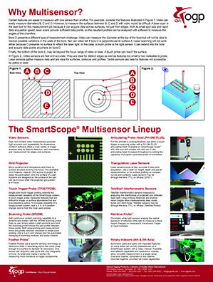


Get the product asset
Product Selector
Click-to-answer questions guide you through selecting the right product for your application.


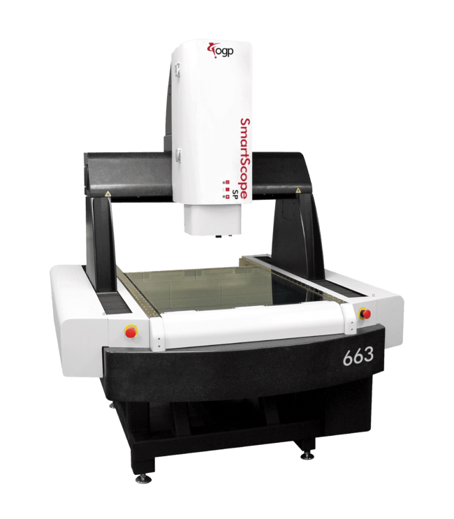
Standard: 650 x 660 x 300 mm
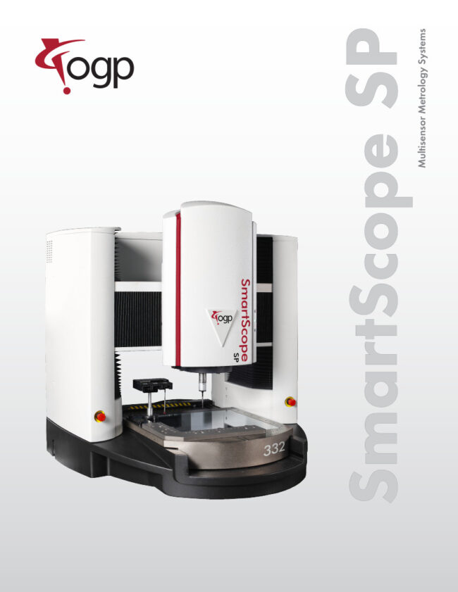
SmartScope® SP systems are designed for optimum scanning probe performance. Starting with a rigid base structure, the system mechanics are designed to optimize dynamic data acquisition critical to scanning probe performance. Most performance specifications for SP models are according to ISO 10360 standards.
SmartScope SP 663 is a moving bridge system designed for larger, heavier parts. During measurement the part remains stationary while the optics and sensors are moved around it. SmartScope SP 663 also offers:
650 x 660 x 300 mm
OGP® SP zoom optics with AccuCentric® autocompensation, one standard front lens and 5.5x optical zoom offer up to 60:1 digital/optical magnification range with maximum 90 mm WD.
2x, 5x lens
All monochromatic LED: substage profile, coaxial
surface, SmartRing™ ring light
LED focus grid illuminator
| SmartScope SP 332 | SmartScope SP 463 | SmartScope SP 663 | |
|---|---|---|---|
| XYZ travel | 300 mm x 300 mm x 250 mm | 450 mm x 610 mm x 300 mm | 650 mm x 660 mm x 300 mm |
| XYZ measuring range with standard lens | 300 mm x 300 mm x 200 mm | 450 mm x 610 mm x 250 mm | 650 mm x 660 mm x 250 mm |
| Machine dimensions | 850 mm x 870 mm x 1025 mm | 1085 mm x 1650 mm x 2060 mm | 1475 mm x 1830 mm x 2060 mm |
| Drive system | 4-axis DC servo drive (X, Y, Z, and zoom) with dual drive, air bearing Z axis | 4-axis DC servo drives (X, Y, Z, and zoom) | 4-axis DC servo drive (X, Y, Z, and zoom) |
| XYZ scale resolution | Standard: 0.1 µm; including dual Z-axis scales; Optional: 0.05 µm | Standard: 0.1 µm; Optional: 0.05 µm | Standard: 0.1 µm, including dual Y-axis scales; Optional 0.05 µm |
| System weight | 160 kg | 1160 kg | 1800 kg |
| Shipping weight | 230 kg | 1400 kg | 2300 kg |
| Worktable | Hardcoat worksurface with tapped fixture holes and removable glass insert | ||
| Worktable payload | 30 kg | 50 kg | 130 kg |
| Rotary axis | Optional Miniature Servo rotary, or MicroTheta™ rotary | Optional Miniature Servo rotary, MicroTheta rotary, or Heavy Duty rotary and Dual Rotary indexers. Consult the factory for complete information about available rotary indexer combinations. | |
| Power requirements | 100-120 VAC or 200-240 VAC, 50/60 Hz, 1 phase, 900 W | 100-120 VAC or 200-240 VAC, 50/60 Hz, 1 phase, 1500 W | 100-120 VAC or 200-240 VAC, 50/60 Hz, 1 phase, 1100 W |
| Compressed air requirements (332 model only) |
Air supply pressure: 0.45 MPa; Minimum Flow capacity: 32 l/min; Air quality ISO 8573-1:2010 Class 4.3.4 or better Optional: Air dryer kit |
||
| Rated environment | Temperature: 18-22 °C, stable to ± 1 °C; Maximum rate of temperature change: 0.5 °C / hour, maximum vertical thermal gradient: 1 °C / meter. Humidity: 30-80%; Vibration <0.001g below 15 Hz | ||
| Safe operating environment | Temperature: 15-30 °C, non-condensing | ||
| Standard | Optional | |
|---|---|---|
| Optics | Zoom optics with AccuCentric® auto-compensation, 1x standard front lens and 5.5x optical zoom offer up to 60:1 digital/optical magnification range with maximum 90 mm working distance | Replacement/Laser Lenses: 2x (38 mm working distance), 5x (16 mm working distance) |
| Illumination | All monochromatic LED: substage profile, coaxial surface, SmartRing™ ring light | LED focus grid illuminator |
| Camera | 5 MP monochrome digital metrology camera | |
| Field of view size Low optical zoom High optical zoom Max digital zoom |
1x: 12.1 mm x 10.1 mm 2.2 mm x 1.8 mm 0.20 mm x 0.16 mm |
2x: 4.7 mm x 3.9 mm 0.9 mm x 0.7 mm 0.08 mm x 0.06 mm 5x: 0.9 mm x 0.7 mm 0.43 mm x 0.35 mm 0.04 mm x 0.03 mm |
| Scanning sensors | QVI® scanning controller, SP25M scanning probe; 3 position change rack; calibration kit including kinematic mount and certified 25 mm sphere; SP25 scanning probe kit including SM25-2 scanning module, SH25-2 stylus holder (x2), and M3 D3 x L21 ruby stylus | 6 position change rack; additional SM25-1, SM25-3, SM25-4, SM25-5, TM25 scanning and touch modules, stylus holders, and styli |
| Laser sensors | TeleStar® Plus TTL laser adapter (includes laser pointer), TeleStar Plus interferometric TTL laser | |
| Controller | Windows® based, with up-to-date processor, on board networking/communication ports and integral QVI scanning controller for laser and tactile scanning; multifunction handheld controller for operator control | |
| Controller options | 24” flat panel monitor, keyboard, 3-button mouse. Ergonomic sit-stand operator workstation for 463 and 663 models. |
Dual 24” flat panel monitors; granite / laminate operator workstation for benchtop 332 model. |
| Software | - ZONE3® Express 3D Metrology Software - QVI Portal | Metrology Software: ZONE3 Prime, ZONE3 Pro Productivity Software: EVOLVE® Suite (Design, Manufacturing, SmartProfile®, SPC) Offline Software: ZONE3 |
Performance and Accuracy Specifications1
| SmartScope SP Model | 332 | 463 | 663 | |
|---|---|---|---|---|
| Optical (per ISO 10360-7:2011)5 | ||||
| X or Y length measurement errors2,3,4 | MPE(EUX[Y]) | (1.5 + 5L/1000) µm | (1.5 + 5L/1000) µm | (2.0 + 5L/1000) µm |
| XY length measurement errors2,3,4 | MPE(EUXY) | (1.9 + 5L/1000) µm | (1.9 + 5L/1000) µm | (2.4 + 5L/1000) µm |
| Length measurement errors2,3,9 | MPE(EU) | (3.9 + 5L/1000) µm | (3.4 + 5L/1000) µm | (4.4 + 5L/1000) µm |
| Repeatability of XY length measurement errors3,4 | MPL(RUXY) | 1.5 µm | 1.5 µm | 2.0 µm |
| Probing error | MPE(PF2D) | 1.9 µm | 1.9 µm | 1.9 µm |
| Probing error of imaging probe | MPE(PFV2D) | 1.2 µm | 1.2 µm | 1.2 µm |
| Autofocus Performance (per QVI #790218)2,5 | ||||
| Z-linear autofocus accuracy | E1 | (3.8 + 5L/1000) µm | (3.8 + 5L/1000) µm | (3.8 + 5L/1000) µm |
| SP25 Tactile Probe Performance (per ISO 10360-5:2020)6,7 | ||||
| Single stylus form error | MPE(P[Form.Sph.1x25:SS:Tact]) | 3.8 µm | 2.5 µm | 3.0 µm |
| Scanning mode form error | MPE(P[Form.Sph.Scan:PP:Tact]) | 4.5 µm | 2.5 µm | 3.5 µm |
| Time for scanning mode form error | MPL(τ[Sph.Scan:PP:Tact]) | 70 sec | 70 sec | 75 sec |
| TeleStar® Plus Laser Performance (per ISO 10360-8:2013)8 | ||||
| Probing size error | MPE(P[Size.Sph.1x25:Tr:ODS]) | 3.5 µm | 3.5 µm | 3.5 µm |
Last updated: July 2025